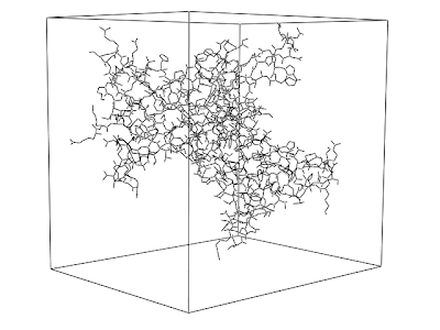
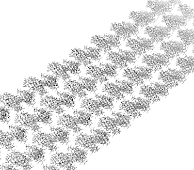
The below picture was obtained with the following Jmol script.

load 1PDB.pdb
load APPEND nwSurface.xyz
model all
axes on
select protein
boundbox {1.1} on
The protein is surrounded by its boundbox. What I now want is to mark the three of the sides of the bound box, as I indicated with arrows added with paint. Maybe the boundbox and the arrows could also be separate "objects" (?), generated on the fly from the structure.
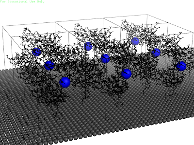
The point is, now the user could click a radio button indicating that the protein is oriented with its (red/green) face towards the wire. If he is not happy with that, he could click the rotate button, returning the box/protein/ensemble ensemble to be oriented with the (red/blue) face towards the wire (for now rotations by 90° is fine). If it is this orientation he expects (depending maybe on binding sites in the protein) he then would click the red/blue radio button and submit the form. Depending on the selected radio button, the appropriate distance of the center of the box to the wire can be obtained.
After a little trying, the following turned out.

The command used for the red vector is
draw xVec vector {-58.19/2.0, -47.57/2.0, -54.71/2.0} {58.19, 0.0, 0.0} width 5.0 color red
What I now require is to have the vectors rotate together with the protein, so maybe the easiest is to have the vectors be part of the protein structure.


